


Ý nghĩa độ nhạy của loadcell
Loadcell là 1 chuyển đổi đo áp lực, gồm 1 cảm biến đàn hồi kết hợp với 1 chuyển đổi đo, chuyển đổi đo thường là cảm biến tenzo, cảm biến đàn hồi thường cấu tạo từ 4 cảm biến đo biến dạng (4 điện trở tenzo mắc theo hình cầu), trong đó có 2 cảm biến chịu biến dạng kéo và 2 cảm biến chịu biến dạng nén. Trong giới hạn làm việc, đặc tính của loadcell được xem như là tuyến tính. Cần xem kĩ các thông tin về độ nhạy, giới hạn đo ghi trên loadcell khi sử dụng.
Với 1 hệ thống nhiều loadcell như trên, người ta thường dùng 1 hộp nối dây (gọi là Junction Box), tùy từng loại mà có thể kết nối được 4,6,8... loadcell lại với nhau. Nguyên tắc của Junction Box là cộng tất cả các tín hiệu thu được từ các loadcell nối vào nó rồi chia trung bình để tìm ra khối lượng chính xác của vật cần cân.
THE STRAIN GAUGE The strain gauge has been in use for many years and is the fundamental
sensing element for many types of sensors, including pressure sensors,
load cells, torque sensors, position sensors, etc.
The majority of strain gauges are foil types, available in a wide choice
of shapes and sizes to suit a variety of applications. They consist of a
pattern of resistive foil which is mounted on a backing material. They
operate on the principle that as the foil is subjected to stress, the
resistance of the foil changes in a defined way.
The strain gauge is connected into a Wheatstone Bridge circuit with a combination of four active gauges (full bridge), two gauges (half bridge),
or, less commonly, a single gauge (quarter bridge). In the half and
quarter circuits, the bridge is completed with precision resistors.
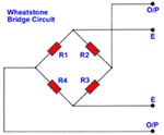
The complete Wheatstone Bridge is excited with a stabilised DC supply
and with additional conditioning electronics, can be zeroed at the null
point of measurement. As stress is applied to the bonded strain gauge,
a resistive changes takes place and unbalances the Wheatstone Bridge.
[Chỉ có thành viên mới có thể nhìn thấy đường links. ]
This results in a signal output, related to the stress value. As the signal
value is small, (typically a few millivolts) the signal conditioning
electronics provides amplification to increase the signal level to 5 to 10
volts, a suitable level for application to external data collection systems
such as recorders or PC Data Acquistion and Analysis Systems.

Some of the many Gauge Patterns available
Most manufacturers of strain gauges offer extensive ranges of differing
patterns to suit a wide variety of applications in research and industrial
projects.
They also supply all the necessary accessories including preparation
materials, bonding adhesives, connections tags, cable, etc. The bonding
of strain gauges is a skill and training courses are offered by some suppliers.
There are also companies which offer bonding and calibration services,
either as an in-house or on-site service.
More about the Strain Gauge...
If a strip of conductive metal is stretched, it will become skinnier and
longer, both changes resulting in an increase of electrical resistance
end-to-end. Conversely, if a strip of conductive metal is placed under
compressive force (without buckling), it will broaden and shorten. If
these stresses are kept within the elastic limit of the metal strip (so
that the strip does not permanently deform), the strip can be used as
a measuring element for physical force, the amount of applied force
inferred from measuring its resistance.
Such a device is called a strain gauge. Strain gauges are frequently used
in mechanical engineering research and development to measure the
stresses generated by machinery. Aircraft component testing is one area
of application, tiny strain-gauge strips glued to structural members,
linkages, and any other critical component of an airframe to measure
stress. Most strain gauges are smaller than a postage stamp, and they
look something like this:
[Chỉ có thành viên mới có thể nhìn thấy đường links. ]A strain gauge's conductors are very thin: if made of round wire, about
1/1000 inch in diameter. Alternatively, strain gauge conductors may be
thin strips of metallic film deposited on a nonconducting substrate
material called the carrier. The latter form of strain gauge is represented
in the previous illustration. The name "bonded gauge" is given to strain gauges that are glued to a larger structure under stress (called the test specimen) The task of bonding strain gauges to test specimens may
appear to be very simple, but it is not. "Gauging" is a craft in its own
right, absolutely essential for obtaining accurate, stable strain measurements. It is also possible to use an unmounted gauge wire
stretched between two mechanical points to measure tension, but this technique has its limitations.
Typical strain gauge resistances range from 30 Ohms to 3 kOhms (unstressed). This resistance may change only a fraction of a percent
for the full force range of the gauge, given the limitations imposed by
the elastic limits of the gauge material and of the test specimen. Forces
great enough to induce greater resistance changes would permanently
deform the test specimen and/or the gauge conductors themselves, thus
ruining the gauge as a measurement device. Thus, in order to use the
train gauge as a practical instrument, we must measure extremely small
changes in resistance with high accuracy.
Such demanding precision calls for a bridge measurement circuit. Unlike
the Wheatstone bridge shown in the last chapter using a null-balance
detector and a human operator to maintain a state of balance, a strain
gauge bridge circuit indicates measured strain by the degree of
imbalance, and uses a precision voltmeter in the center of the bridge
to provide an accurate measurement of that imbalance:
Typically, the rheostat arm of the bridge (R2 in the diagram) is set
at a value equal to the strain gauge resistance with no force applied.
The two ratio arms of the bridge (R1 and R3) are set equal to each
other. Thus, with no force applied to the strain gauge, the bridge
will be symmetrically balanced and the voltmeter will indicate zero
volts, representing zero force on the strain gauge. As the strain
gauge is either compressed or tensed, its resistance will decrease
or increase, respectively, thus unbalancing the bridge and producing
an indication at the voltmeter. This arrangement, with a single element
of the bridge changing resistance in response to the measured variable (mechanical force), is known as a quarter-bridge circuit.
As the distance between the strain gauge and the three other
resistances in the bridge circuit may be substantial, wire resistance
has a significant impact on the operation of the circuit. To illustrate
the effects of wire resistance, I'll show the same schematic diagram,
but add two resistor symbols in series with the strain gauge to
represent the wires:
The strain gauge's resistance (Rgauge) is not the only resistance being
measured: the wire resistances Rwire1 and Rwire2, being in series with
Rgauge, also contribute to the resistance of the lower half of the
rheostat arm of the bridge, and consequently contribute to the
voltmeter's indication. This, of course, will be falsely interpreted by
the meter as physical strain on the gauge.
While this effect cannot be completely eliminated in this configuration,
it can be minimized with the addition of a third wire, connecting the right
side of the voltmeter directly to the upper wire of the strain gauge:
Because the third wire carries practically no current (due to the
voltmeter's extremely high internal resistance), its resistance will not
drop any substantial amount of voltage. Notice how the resistance
of the top wire (Rwire1) has been "bypassed" now that the voltmeter
connects directly to the top terminal of the strain gauge, leaving only
the lower wire's resistance (Rwire2) to contribute any stray resistance
in series with the gauge. Not a perfect solution, of course, but twice
as good as the last circuit!
There is a way, however, to reduce wire resistance error far beyond
the method just described, and also help mitigate another kind of
measurement error due to temperature. An unfortunate characteristic
of strain gauges is that of resistance change with changes in
temperature. This is a property common to all conductors, some more
than others. Thus, our quarter-bridge circuit as shown (either with
two or with three wires connecting the gauge to the bridge) works
as a thermometer just as well as it does a strain indicator.
If all we want to do is measure strain, this is not good. We can
transcend this problem, however, by using a "dummy" strain gauge
in place of R2, so that both elements of the rheostat arm will change
resistance in the same proportion when temperature changes, thus
canceling the effects of temperature change:
- Chức Năng Và Nhiệm Vụ Của Loadcell
- Cách Đo Độ Mủ Cao Su
- Hướng Dẫn Sử Dụng Cân Treo Điện Tử
- Hướng dẫn sử dụng Đầu Cân KingBird
- Hướng dẫn sử dụng Đầu Cân A9P
- Hướng dẫn sử dụng Đầu Cân A12 LCD
- Hướng dẫn sử dụng Đầu Cân, Màn Hình YHT3
- Hướng dẫn sử dụng Cân Đếm JCL
- Hướng Dẫn Sử Dụng Cân Đo Tuồi Vàng
- Hướng dẫn sử dụng Cân JWN
- Sửa Cân Bàn Điện Tử
- Sửa Cân Sàn Điện Tử
- Sửa Cân Chống Nước
- Sửa Cân Nông Sản
- Sửa Cân Móc Điện Tử
- Sửa Cân Phòng Thí Nghiệm
- Sửa Cân Đếm Điện Tử
- Sửa Cân Tính Tiền
- Sửa Cân Vàng Điện Tử
- Sửa Cân Mủ Cao Su
- Sửa Cân Sức Khỏe
- Sửa Cân Bỏ Túi, Cân Mini
- Sửa Cân Nhà Bếp
- Sửa Cân Xe Nâng
- Sửa Cân Gia Súc
- Sửa Cân Ô Tô
- Sửa Cân Ô Tô Kiểu Chìm
- Sửa Cân Bàn
- Sửa Cân Phân Tích
- Sửa Đầu Cân Điện Tử
- Sửa Cân Xe Tải
Tel: (84-028) 35.030609
Hotline:098.7069696 -Zalo: 094.7069696


-
Trực tuyến:2
-
Hôm nay:214
-
Tuần này:2054
-
Tuần trước:2290
-
Tháng trước:4164
-
Tất cả:2112689